Principle of Rock Slope Design – Introduction

I. Introduction

A variety of engineering activities require excavation of rock cuts. In civil engineering,
projects include transportation systems such as highways and railways, dams for power production and water supply, and industrial and urban development. In mining, open pits account for the
major portion of the world’s mineral production. The dimensions of open pits range from areas of a few hectares and depths of less than 100 m, for some high grade mineral deposits and quarries in urban areas, to areas of hundreds of hectares and depths as great as 800 m, for low grade ore deposits. The overall slope angles for these pits range from near vertical for shallow pits in good quality rock to flatter than 30◦ for those in very poor quality rock.
Figure 1.1 shows two typical rock slopes.
Figure 1.1(a) is a rock cut, with a face angle of about 60◦, supported with tensioned anchors
incorporating reinforced concrete bearing pads about 1 m2 that distribute the anchor load on
the face. The face is also covered with shotcrete to prevent weathering and loosening between the
bolts. Water control measures include drain holes through the shotcrete and drainage channels on
the benches and down the face to collect surface run-off. The support is designed to both ensure
long-term stability of the overall slope, and minimize rock falls that could be a hazard to traffic.
Figure 1.1(b) shows the Palabora open pit in South Africa that is 830 m deep and an overall
slope angle of 45–50◦; this is one of the steepest and deepest pits in the world (Stewart et al., 2000).


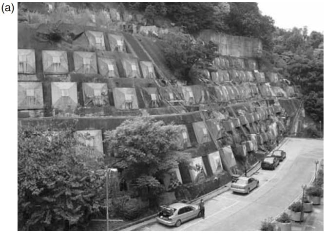
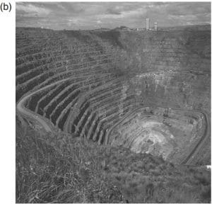
Figure 1.1 Examples of rock slopes: (a) rock slope in Hong Kong supported with tensioned rock anchors and reinforced concrete reaction blocks, and shotcrete (photograph by Gary Fu); and (b) 830 m deep Palabora open pit copper mine, South Africa. (Photograph courtesy: Rio Tinto Ltd.)

The upper part of the pit is accessed via a dual ramp system, which reduces to a single ramp in
the lower part of the pit. In addition to these man-made excavations, in mountainous terrain the stability of natural rock slopes may also be of concern. For example, highways and railways located in river valleys may be located below such slopes, or cut into the toe, which may be detrimental to stability. One of the factors that may influence the stability of natural rock slopes is the regional tectonic setting. Factors of safety may be only slightly greater than unity where there is rapid uplift of the land mass and corresponding down-cutting of the watercourses, together with earthquakes that loosen and displace the slope. Such conditions exist in seismically active areas such as the Pacific Rim, the Himalayas and central Asia. The required stability conditions of rock slopes will vary depending on the type of project and the consequence of failure. For example, for cuts above a highway carrying high traffic volumes it will be important that the overall slope be
stable, and that there be few if any rock falls that reach the traffic lanes. This will often require
both careful blasting during construction, and the installation of stabilization measures such as
rock anchors. Because the useful life of such stabilization measures may only be 10–30 years,
depending on the climate and rate of rock degradation, periodic maintenance may be required for
long-term safety. In contrast, slopes for open pit mines are usually designed with factors of safety  in the range of 1.2–1.4, and it is accepted that movement of the slope and possibly some partial
slope failures will occur during the life of the mine. In fact, an optimum slope design is one that
fails soon after the end of operations. In the design of cut slopes, there is usually little
flexibility to adjust the orientation of the slope to suit the geological conditions encountered in
the excavation. For example, in the design of a highway, the alignment is primarily governed
by such factors as available right-of-way, grades and vertical and horizontal curvature. Therefore,
the slope design must accommodate the particular geological conditions that are encountered
along the highway. Circumstances where geological conditions may dictate modifications to
the slope design include the need for relocation where the alignment intersects a major landslide
that could be activated by construction. With respect to open pit slope design, the pit must
obviously be located on the ore body, and the design must accommodate the geological conditions that exist within the area of the pit. This may require different slope designs around
the pit. The common design requirement for rock cuts is to determine the maximum safe cut face angle compatible with the planned maximum height. The design process is a trade-off between stability and economics. That is, steep cuts are usually less expensive to construct than flat cuts because there is less volume of excavated rock, less acquisition of right-of-way and smaller cut face areas. However, with steep slopes it may be necessary to install extensive stabilization measures such as rock bolts and shotcrete in order to minimize both the risk of overall slope instability and rock falls during the operational life of the project.
1.1.1 Scope of book
The design of rock cuts involves the collection of geotechnical data, the use of appropriate design
methods, and the implementation of excavation methods and stabilization/protection measures
suitable for the particular site conditions. In order to address all these issues, the book is divided
into three distinct sections that cover respectively design data, design methods and excavation/support procedures. Details of the main topics covered in each section are as follows:

(a) Design data
• Geological data of which structural geology is usually the most important. This
information includes the orientation of Principles of rock slope design 3 discontinuities and their characteristics such as length, spacing, roughness and infilling. Chapter 2 discusses interpretation of these data, while Chapter 3 describes methods of data collection.
• Rock strength with the most important parameter being the shear strength of
discontinuity surfaces or rock masses, and to a lesser extent the compressive
strength of the intact rock (Chapter 4).
• Ground water conditions comprise the likely ground water level within the
slope, and procedures to drain the slope, if necessary (Chapters 5 and 12).

(b) Design methods
• Design methods for rock slopes fall into two groups—limit equilibrium analysis and numerical analysis. Limit equilibrium analyses calculates the factor of safety of the slope and different procedures are used for plane, wedge, circular and toppling failures; the type of failure is defined by the geology of the slope (Chapters 6–9). Numerical analysis examines the stresses and strains developed in the slope, and stability is assessed by comparing the stresses in the slope with the rock strength (Chapter 10).

(c) Excavation and stabilization
• Blasting issues relevant to slope stability include production blasting, controlled blasting on final faces, and in urban areas the control of damage from ground vibrations, flyrock and noise (Chapter 11).
• Stabilization methods include rock reinforcement with rock anchors and dowels, rock removal involving scaling and trim blasting, and rock fall protection measures comprising ditches, fences and sheds (Chapter 12).
• Monitoring of slope movement is often an important part of slope management in open pit mines. Surface and sub-surface monitoring methods are discussed, as well as interpretation of
the data (Chapter 13).
• Civil and mining applications are discussed in Chapters 14 and 15, respectively, which describe examples of slope design, including stabilization methods and movement monitoring programs.
The examples illustrate the design procedures discussed in the earlier chapters. Also included in the book are a series of example problems demonstrating both data analysis and design methods.

1.1.2 Socioeconomic consequences of slope failures
Failures of rock slopes, both man-made and natural, include rock falls, overall slope instability and landslides, as well as slope failures in open pit mines. The consequence of such failures can
range from direct costs of removing the failed rock and stabilizing the slope to possibly a wide
variety of indirect costs. Examples of indirect costs include damage to vehicles and injury to passengers on highways and railways, traffic delays, business disruptions, loss of tax revenue due to decreased land values, and flooding and disruption to water supplies where rivers are blocked by
slides. In the case of mines, slope failures can result in loss of production together with the cost of
removal of the failed material, and possible loss of ore reserves if it is not possible to mine the pit
to its full depth. The cost of slope failures is greatest in urbanized areas with high population densities where even small slides may destroy houses and block transportation routes (Transportation Research Board, 1996). In contrast, slides in rural areas may have few indirect costs, except perhaps the costs due to the loss of agricultural land. An example of a landslide that resulted in severe economic costs is the 1983 Thistle Slide in Utah that resulted in losses of about $200 million when the landslide dammed the Spanish Fork River severing railways and highways, and flooding the town  of Thistle (University of Utah, 1985). An example of a landslide that resulted in both loss of life and economic costs is the Vaiont Slide in Italy in 1963. The slide inundated a reservoir sending a wave over the crest of the dam that destroyed five villages and took about 2000 lives (Kiersch, 1963; Hendron and Patton, 1985).
A country that experiences high costs of rock falls and landslides is Japan. This country has
both highly developed infrastructure and steep mountainous terrain, and in addition, there are
frequent triggering events such as high rainfall, freeze–thaw cycles and ground shaking due to
earthquakes. Documentation of major landslides between 1938 and 1981 recorded total losses
of 4834 lives and 188,681 homes (Ministry of Construction, Japan, 1983).

References : Wyllie, Duncan C. And Mah, Christopher W  (2004) Rock slope engineering – civil and mining 4th edition, London and New York

Blasting Design

Blasting Design
ROCK Breaking MECHANISM
1. The process of solving Tk I (Dynamic Loading)
When the rhino explodes, high P destroys the rock around the blast hole. The shock wave propagates at a rate of 3000-5000 m / s resulting in tangential stresses that cause fractures that radiate from the explosion hole. Fracture of finger I occurs in 1-2 ms

2. Tk II Solving Process (Quasi-static loading)
with respect to the shock wave leaving the blast hole in process I is +. When it reaches the plane of the beam it is reflected, the pressure drops rapidly, then changes to – and a tensile wave occurs. The wave of attraction travels back to the rock. Because rocks are less resistant to tension than pressure, primary fractures will occur due to the tensile stress of the reflected waves. If the tensile stress is strong enough it will cause slabbing / spalling in the free plane. Process I and II are a function of the shock wave energy: preparing the rock with a number of small fractures for the final breaking process.

3. Tk III (Release of Loading) Breaking Process
Under the high pressure of the blasting gases the primary radial fracture (TkII) is rapidly expanded by the combination of the effects of tensile stress due to radial compression and splitting. If the mass of the rock in front of the blast hole fails to maintain its position to move forward, the high compressive stress in the rock will be released like a spiral of pressed wire and then released. The effect of the loose rock causes high tensile stress in the rock mass which will continue to break the results that have occurred in the Tk II breaking process. The fracture resulting in Tk II cracking causes a weak field to initiate major fragmentation reactions in the blasting process.

3.2. EXPLOSION DESIGN
– Blasting geometry
– Drilling and blasting patterns
– rhino necessities and equipment
-production blasting
-Post production handling

3.2.1. Uncontrollable Design Factors
-Geology: rock type, rock mineral type, rock weathering process
Weathering Factor:
Mineral components, climatological factors, grain size / min, rock porosity and permeability, relationship / contact between rocks, rock dissolving properties
-The nature of rock strength
– Rock Discontinuity
– Weather conditions
-Water effect

3.2.2. Controllable design factor
1. Drilling Geometry
-Diameter of blast hole, depth of blast hole, inclination of blast hole, level height, drilling pattern
2. Blasting geometry
-Burden, spacing, Fill length, Subdriling, steaming, blasting pattern, delay timing, ignition sequence
3. Rhino and Accessories
-Type & strength of rhino, detonator, etc.

I. Geometry of Drilling
a. Blast Hole Diameter:
The determination of the diameter depends on:
-Volume of rock mass to be dismantled
-level height and input configuration
-tk the desired fragmentation
– Drilling machines available
-capacity of the loaders that will handle blasting material
Small Explosive Lub Diameter:
-only for ta / quarry with small product volume
-krn B n S meeting then the number of blast holes>
-High drilling and booming costs
Advantages of Big Explosion Hole Diameter (5 inch />):
-Fill diameter> so that the det> speed is high
-Drilling productivity> high
-Mechanical filling system
-Relatively low drilling and blasting costs
-The productivity of the loading tool can be increased due to the productive work area
b. Explosion Hole Depth
Adjusted to the height of the level. The depth of the blast hole must be> than the cascade height.
c. Burst Hole Inclination
Can be upright / tilted. The direction of alignment of the boreholes in the ladder should be parallel to ensure burden and spacing absorption in the blasting geometry.
Advantages of upright blast holes:
-for the same level height, the length of the blast hole is shorter than the inclined blast hole
-Less likelihood of throwing rocks
-easier to work with
Loss:
-The crushing along the blast hole is uneven
-> produce lumps in the stemming area
-Creating bulges on the floor level
-Create backward cracks with ground vibrations.
d. Drilling Pattern
-Pattern parallel drilling (parallel):
pattern by placing the explosive holes in a sequence and parallel to the burden
-Staggered drilling pattern
the exploding hole alternating drilling pattern is located in a sequence which is not parallel.

2. Blasting geometry

A. Blasting Geometry C.J. KONYA
1.Burden:
the shortest perpendicular distance between the rhino’s load and the closest free plane / direction to which the bat will be thrown.
B = 3.15 De (Sge / SGr) 0.33
B = [(2Sge / SGr + 1,5)] De
B = 0.67 De (Stv / SGr) 0.33
B: burden (ft)
De: Diameter of explosion (inch)
SGe: SG rhino
Stv: relative bulk strength (ANFO = 100)
Be = Kr x Kd x Ks x B
Kd: factor to lap bat position
Cr: factor thd number of lubricants
Ks: factor of geological structure

2.Spacing, S
The distance between the hole in 1 gram which is parallel to the free bid.
S = (L + 7B) / 8
S: spacing(m), L: level height, B: burden

3.Stemming, T
The column covering the lub ldk on top of the rhino stuffing column
T = 0.45 x De x (Stv / SGr) to the power of 0.33 (Ft)

4.Subdrilling, J
Mr pjg lub ldk which is below the level floor which serves to make the tier floor relatively flat after blasting.
J = 0.3 B (m)

5. Time Delay
To get the difference in play time between 2 holes, it is not possible to obtain it in a row.
Tr = Tr x B
Tr: time delay between brs lub ldk (ms)
Tr: delay time constant

6. The use of rhinos
To determine the number of rhinos used in each hole, the loading density is not determined.
de = 0.34 x SGe x De squared
de: loading density (lb / ft)
Determine the number of rhinos per hole:
E = Pc x de x N
E: number of rhinos
Pc: height of stuffing column (m)
de: loading density (kg / m)
N: number of lub ldk

B. Blasting Geometry R.L. ASH

DISPARATION FEES
Total drilling costs with blasting costs.

Blasting Fee:
1. The cost of primary + explosives
2. Equipment costs:
-Detonator, Sb Explosion, Sb Api, Nonel, M-S Delay
3. Depression Tool: Exploder
4. Operators (explosives) N Assistants

TUNNELING

SEWDISH METHOD
Nomenclature

CUT HOLE – parallel hole cut

V CUT

Functions:
Cut Hole: blown to make a free hole
Cut Spreader hole: widens the free field
Stopping hole: blasting the center of the opening hole section
Roof hole: blasting the roof
Wall hole: detonates left and right
Floor Hole: blow up the floor

Blasting Drilling Patterns in Tunnels

5. CONTROLLED EXPLOSION
The blasting technique used / the drilling and blasting pattern is arranged in such a way as to regulate the overbreak and to regulate the stability of the rock formation that is left behind (can be in the form of rock)

Controlled Blasting Method:
A. Line Drilling
Aims to create a weak plane through which rock can be dismantled. Aligned boreholes help reflect further waves, reducing the crushing effect of rock beyond the demolition boundary

B. Cushion Blasting
The blasting method is similar to line drilling, the diameter is 51-89 mm, the difference: in custhon blasting, the tight holes are filled with a little rhino and are well distributed, after being filled they are clogged with soil, then compacted, and are blown up after the production hole is blown.
Advantages:
-The number of drill holes is needed a little
-On rock nitrogen application of CB is better The result (Bat obtained is better)
Loss:
– expensive because you have to move the blasting product
-Production delay due to excavation for the entire area can not be done at once

C. Smooth Blasting
Most famous and applied to tunneling (making tunnels by means of blasting) and the most recent blasting.
Difference between SB and CB:
-In SB the stemming holes are at the top but not the whole part of the hole, so that there is a hole filled with air.
-SB, the contents are below

D. Presplitting

In a large hole filled with rhinos, the hoe complete is blown first so that a fracture occurs

If the part above is detonated there will be a shock wave. The shock waves that arise will be reflected so as not to disturb the surrounding buildings

source: http://alibie-analyzer.blogspot.com

Mining Explosives – Drilling & Blasting

Explosives
1.1 LIMITATION
1.1.1. Deck
-A stable body which when subjected to proper stimulation will quickly change from pdt / liquid to hot n expansive gas which results in surrounding tech (Grolier).
-Bhn / camp which can react in a short time and produce energy in large quantities because there is a very large volume of gas at a very high T followed by very high mechanical, visual and acoustic effects (Berta G)
-Bhn / substances which are in the form of pdt, liquid, gas or camp which when subjected to an action in the form of heat, the impact / friction will change chemically into other substances which are mostly or entirely gaseous and these changes occur in a very short time with the effect of pns and P which is very high (Presidential Decree No. 5 year 1998)

1.1.2.Blasting Agent

1.Dry Blasting Agent (ANFO)
A granular camp consisting of combustion / oxidizing materials intended for detonation, where all the camps cannot be classified as rhinos and the resulting camp cannot be detonated using blasting cap No. 8.

2.Slurry / Emulsion / Watergel Blasting Agent
Camp oxidizing agents (NaNO3, NHNO3), fuel sensitizer, and about 15-20% water in + gelling agent cause slurry on water.

1.2 MATERIALS AND COMP
Commercial rhino contains compound camps containing C, H, N, O. Kmd to obtain the ttu effect sometimes at +2 sensitizers Na, Al, Ca.

1.2.1. Zero Oxygen Balanced
In rhino get oxygen in the right amount so that during the whole reaction H will form H2O, C? CO2 and N? N2 is free.
3NH4NO3 + CH2? 7H2O + CO2 + 3N2
Negative Oxigen Balance:
2NH4NO3 + CH2? 5H2O + N2 + CO
Positive OB
5NH4NO3 + CH2? 11H2) + CO2 + 4N2 + 2NO
ZOB formula:
Rhino is only found in CHNO element
ZOB = Oo-2Co-0.5Ho
If there are additional elements (Na, Ca, Al)
ZOB = (Oo – 0.5Nao – Cao – …) –2Co – 0.5Ho

1.2.2 Blasting reaction
The reaction that generates heat and generally the heat generated is very high, the gas forms very quickly and produces very high pressure.
-Deflagration: shows a high-speed combustion reaction accompanied by a very fast gas expansion in a limited space so that it creates a very large pressure and causes a lifting effect which is proportional to the combustion process.
-Detonation: describes the propagation process of shock gel through a rhino column which is followed by a chemical reaction that adds energy to stimulate shock gel propagation, followed by gas expansion in a very short time.

1.3. CLASSIFICATION OF BADAK
Presidential Decree No. 5/1988 also Decree of the Minister of Defense and Security No SKEP / 974? VI? 1988 divides rhinos into:
1. Industrial Explosive Decks
2. Military Explosives Deck

Industrial Rhino Distinguished according to its shock gel (Jimeno):
1. Sudden Rapid (Rapid n Detonating Explosives)
speed 2000-7000 m / sec and differentiated into primary (high energy and sensitive, for detonator and print primers such as mercury fulminate, PETN, Pentolite) and secondary which is less sensitive is used for the filling of explosive holes
2Badak Slow (Slow n Deflagrating Exp)
Kecwh below 2000 m / s

Rhino according to Manon:
1. High explosives
Detonation rate: 1600-7500 m / s, properties: detonation (propagation of the shock gel) and produces a shattering effect
2. Weak deck (Low Exp)
Reaction rate less than 1600 m / s, Characteristics: deflagration (chemical reaction that is very fast and causes a heaving effect)

Industrial Rhino based on its composition:
1. Black Powder [8C + 3S + 10KNO3? 3K2CO3 + 2K2CO3 + CO2 + SN2]
2. Dinamite
-Straight Dinamite: dynamite with NG comp (20-57%) and NaNO3 as oxygen carrier (59-23%).
-Gelatine Dinamite: dynamite with gelatine (NG and nitrocellulose) blasting at + NaNO3 / KNO3.
-Amonium Gelatine Dinamite: dynamite with gelatine comp blasting di + NH4NO3
3. Permissible Explosive
Rhino is strong for TBT especially TA BB with Comp Ammonium Gelatine dynamite in + flame depressant (NaCl) to get low T, less gas Vol and ignition as short as possible.
BG + NH4NO3 + NaCl
4. Blasting agent? ANFO, ALANFO, Slurry / watergel / emulsions, heavy ANFO

1.4. BADAK PROPERTIES

1. Strength
related to the energy content possessed by the rhino and the size of the rhino’s ability to do work (%)
2.Kec Detonation
small detonation gel that breaks along the rhino filling column (m / s).
Factors: type of rhino (grain size, body weight), D dodol / D shooting holes, degree of confinement, initial ignition.
3. Sensitivity
Measure the amount of impulse needed for the rhino to start reacting and spread the explosive reaction throughout the stuffing.
Factor: chemical comp, grain size, content bbt, water content, T.
-Sensitivity to impact (sensivity to shock / impact)
-kep to friction (friction)
-kep thd heat (heat)
-Kep to another rhino explosion from that distance (gap sensivity)
4.Bbt Contents Cdk
Comparison between rhino weight and vol (gr / cm3)
-SG: ratio of density of rhino to density of water at standard con- nection (0.6-1.7)
-Stick Count: number of standard lunkhead 1 ¼ “x 8” in 1 50 pound box (232-83)
-Loading density: rhino weight per unit of length.
5. Detonation pressure
The spread of blast wave tech in the rhino stuffing column (Kilobar / kb). Kb: 5-150 kb
6. Water Resistance
The rhino’s ability to withstand water seepage in time without damaging, changing or reducing the sensitivity (clock)

Water resistance level:
-Perfect (excellent) yr on water> 12 hours
-Very good? 8-12 hours
-Good (good)? 4-8 hours
-Enough (Fair)? <4 hours
-Bad (poor) not yr. To water
7. Nature of Toxic Gas
Rhino explodes producing: smoke / fumes
Smoke is insignificant because it only consists of white steam / smoke.
Fumes are yellow and green because they are toxic and contain carbon monoxide CO and nitrogen oxides NO8.

1.5. EXPLOSION EQUIPMENT
the material needed to make the blasting circuit so that the rhino stuffing can be ignited (only for one lighting)
1.detonator
-Electric sec / EBC: instantaneous sec, delay sec
-det is usually used with fire
-power cable
– tape insulator
2.Sb Fire with equipment: ignitor cord, igniter cord connector
3.Sb Explosive: Ms Connector / detonating relay / delay connector.

1.6. EXPLOSION EQUIPMENT
The tools needed to test and ignite the blasting circuit so that they can be used repeatedly.
1. Blasting Machine (DC electrical energy source) along with Ohm-meter, rheostat
2.Cap Crimper
3. Main cable (bus wire, leading wire), namely the cable connecting BM to the blasting circuit.

1.7. ELECTION OF THE BADAK
1. the price of the rhino and its equipment
2. Availability in the market and continuity of supply
3. The characteristics of the bat that will be dismantled
4.Vol bat to be dismantled
5. Working conditions
6.Mslh Circle
7. Applicable regulations

source of rizki martarozi

Measurement Calibration Services – Call 0856 4007 1533

Measurement Calibration Services

Calibration is determining the correctness of the value shown by the measuring instrument by comparing the value with the standard measuring value that has been set nationally or internationally and other materials that have been used as standardization references.
Measuring instrument calibration services – Every industry uses measuring instruments to measure various objects related to the industry. And all measuring instruments require measurements to comply with predetermined standards. This adjustment to the standard of the measuring instrument is called calibration.

Main Purpose of Calibration
Determine the feasibility of measuring instruments
Ensure measurement results comply with national and international standards
Perform detection, provide reports and also sort out each level of measuring instrument accuracy
Determine the amount of the conventional deviation value indicated on the measuring instrument

Benefits of Calibration
Maintain measuring instruments that have been tested so that the standard measuring values ​​remain in accordance with their initial specifications
Can know the difference between the true value and the deviation (deviation) on the measuring instrument
Can increase the company’s credibility
Minimizing product withdrawals that do not comply with standard measurements

Basic Principles of Calibration
Establishing standardization of measurements (referring to national measurement standards or you can also develop their own measuring standards by a laboratory that has been tested and certified)
Set the measured object value
Determine the value of the deviation (deviation)

Broadly speaking, Calibration is a process that is carried out to adjust an instrument or measuring instrument to conform to the measuring standard specified in a certain accuracy. So that when the measuring instrument is used to measure an object, the measuring value pointer is in accordance with the initial measurement results, no less and no more.

In working on the calibrator or the calibration process, a measuring instrument calibration service that has experienced personnel and instruments for calibration is needed. Abdiyasa provides calibration services for measuring and testing instruments

If you are interested in using the measurement service calibration provided by Abdiyasa, please contact our staff directly by using No. Tel / WA 0856 4007 1533

calibration