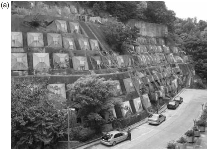
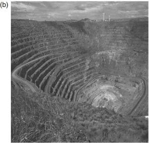
1.2 Principles of rock slope engineering
This section describes the primary issues that need to be considered in rock slope design for civil projects and open pit mines. The basic difference between these two types of project are that in
civil engineering a high degree of reliability is required because slope failure, or even rock falls,
can rarely be tolerated. In contrast, some movement of open pit slopes is accepted if production
is not interrupted, and rock falls are of little consequence.

Figure 1.2 Relationship between slope height and slope angle for open pits, and natural and engineered slopes: (a) pit slopes and caving mines (Sjöberg, 1999); and (b) natural and engineered slopes in China (data from Chen (1995a,b)).
As a frame of reference for rock slope design, Figure 1.2 shows the results of surveys of the
slope height and angle and stability conditions for natural, engineered and open pit mine slopes
(Chen, 1995a,b; Sjöberg, 1999). It is of interest to note that there is some correspondence between the steepest and highest stable slopes for both natural and man-made slopes. The graphs also show that there are many unstable slopes at flatter angles and lower heights than the maximum values because weak rock or adverse structure can result in instability of even low slopes.
1.2.1 Civil engineering
The design of rock cuts for civil projects such as highways and railways is usually concerned
with details of the structural geology. That is, Principles of rock slope design 5 Figure 1.3 Cut face coincident with continuous, low friction bedding planes in shale on Trans Canada Highway near Lake Louise, Alberta. (Photograph by A. J. Morris.) the orientation and characteristics (such as length, roughness and infilling materials) of the joints, bedding and faults that occur behind the rock face. For example,

Figure 1.3 Cut face coincident with continuous, low friction bedding planes in shale on Trans Canada Highway near Lake Louise, Alberta. (Photograph by A. J. Morris.)
Figure 1.3 shows a cut slope in shale containing smooth bedding planes that are continuous over the full height of the cut and dip at an angle of about 50◦ towards the highway. Since the friction angle of these discontinuities is about 20–25◦, any attempt to excavate this cut at a steeper angle than the dip of the beds would result in blocks of rock sliding from the face on the beds; the steepest unsupported cut that can be made is equal to the dip of the beds. However, as the alignment of the road changes so that the strike of the beds is at right angles to the cut face (right side of photograph), it is not possible for sliding to occur on the beds, and a steeper face can be excavated.
For many rock cuts on civil projects, the stresses in the rock are much less than the rock strength so there is little concern that fracturing of intact rock will occur. Therefore, slope design is primarily concerned with the stability of blocks of rock formed by the discontinuities. Intact rock strength, which is used indirectly in slope design, relates to the shear strength of discontinuities and rock masses, as well as excavation methods and costs.
Figure 1.4 shows a range of geological conditions and their influence on stability, and illustrates the types of information that are important to design. Slopes (a) and (b) show typical conditions for sedimentary rock, such as sandstone and limestone containing continuous beds, on which sliding can occur if the dip of the beds is steeper than the friction angle of the discontinuity surface. In (a) the beds “daylight” on the steep cut face and blocks may slide on the bedding, while in (b) the face is coincident with the bedding and the face is stable. In (c) the overall face is also stable because the main discontinuity set dips into the face. However, there is some risk of instability of surficial blocks of rock formed by the conjugate joint set that dips out of the face, particularly if there has been blast damage during construction. In (d) the main joint set also dips into the face but at a steep angle to form a series of thin slabs that can fail by toppling where the center of gravity of the block lies outside the base. Slope (e) shows a typical horizontally bedded sandstone–shale sequence in which the shale weathers considerably faster than the sandstone to form a series of overhangs that can fail suddenly along vertical stress relief joints. Slope (f) is cut in weak rock containing closely spaced but low persistence joints that do not form a continuous sliding surface. A steep slope cut in this weak rock mass may fail along a shallow circular surface, partially along joints and partially through intact rock.

Figure 1.4 Influence of geological conditions on stability of rock cuts: (a) potentially unstable—discontinuities “daylight” in face; (b) stable slope—face excavated parallel to discontinuities; (c) stable slope—discontinuities dip into face; (d) toppling failure of thin beds dipping steeply into face; (e) weathering of shale beds undercuts strong sandstone beds to form overhangs; (f) potentially shallow circular failure in closely fractured, weak rock.
1.2.2 Open pit mining slope stability
The three main components of an open pit slope
design are as follows (Figure 1.5).

Figure 1.5 Typical open pit slope geometry showing relationship between overall slope angle, inter-ramp angle and bench geometry.
First, the overall pit slope angle from crest to toe, incorporates all ramps and benches. This may be a composite slope with a flatter slope in weaker, surficial materials, and a steeper slope in more competent rock at depth. In addition, the slope angle may vary around the pit to accommodate both differing geology and the layout of the ramp. Second, the inter-ramp angle is the slope, or slopes, lying between each ramp that will depend on the number of ramps and their widths. Third, the face angle of individual benches depends on vertical spacing between benches, or combined multiple benches, and the width of the benches required to contain minor rock falls.
Some of the factors that may influence slope design are the slope height, geology, rock strength, ground water pressures and damage to the face by blasting. For example, with each successive push-back of a slope, the depth of the pit will increase and there may need to be a corresponding decrease in the overall slope angle. Also, for slopes on which the ramp is located, the slope angle may be flatter to limit the risk of failures that take out the ramp, compared to slopes with no ramp where some instability may be tolerated. Where there is significant water pressure in the slope, consideration may be given to installing a drainage system if it can be shown that a reduction in water pressure will allow the slope angle to be increased. For deep pits where an increase in slope angle of one or two degrees will result in a saving of several million cubic meters of rock excavation, an extensive drainage system may be justified. Such drainage systems could comprise fans of holes with lengths of hundreds of meters drilled from the slope face, or a drainage adit with holes drilled into the rock above the tunnel.
With respect to the bench face angle, this may be governed by the orientation of a predominant joint set if there are joints that dip out of the face at a steep angle. If this situation does not exist, then the bench angle will be related to the overall slope geometry, and whether single benches are combined into multiple benches. One factor that may influence the maximum height of individual benches is the vertical reach of excavating equipment, to limit the risk accidents due to collapse of the face.
In order to provide a guideline on stable pit slope angles, a number of studies have been carried out showing the relationship between slope angle, slope height and geology; the records also distinguished whether the slopes were stable or unstable (see Figure 1.2). These studies have been made for both open pit mine slopes (Sjöberg, 1999), and natural and engineered slopes in China (Chen, 1995a,b). As would be expected, if the slopes were not selected according to geology, there is little correlation between slope height and angle for stable slopes. However, sorting of the data according to rock type and rock strength shows a reasonable correlation between slope height and angle for each classification.
1.3 Slope features and dimensions
The International Association of Engineering Geology has prepared definitions of landslide features and dimensions as shown in Figures 1.6 and 1.7 (IAEG, 1990; TRB, 1996). Although the diagrams depicting the landslides show soil-type slides with circular sliding surfaces, many of these landslide features are applicable to both rock slides and slope failures in weak and weathered rock. The value of the definitions shown in Figures 1.6 and 1.7 is to encourage the use of consistent terminology that can be clearly understood by others in the profession when investigating and reporting on rock slopes and landslides.
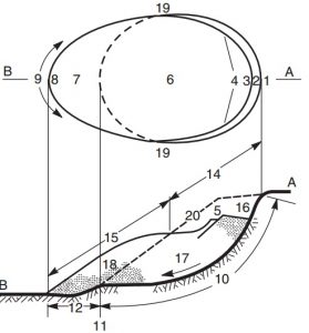
Figure 1.6 Definitions of landslide features: upper portion, plan of typical landslide in which dashed line indicates trace of rupture surface on original ground surface; lower portion, section in which hatching indicates undisturbed ground and stippling shows extent of displaced material. Numbers refer to dimensions defined in Table 1.1 (IAEG Commission on Landslides, 1990).
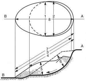
Figure 1.7 Definitions of landslide dimensions: upper portion, plan of typical landslide in which dashed line is trace of rupture surface on original ground surface; lower portion, section in which hatching indicates undisturbed ground, stippling shows extent of displaced material, and broken line is original ground surface. Numbers refer to dimensions defined in Table 1.2 (IAEG Commission on Landslides, 1990).
References : Wyllie, Duncan C. And Mah, Christopher W (2004) Rock slope engineering – civil and mining 4th edition, London and New York