Prinsip Desain Lereng Batuan – 1.2 Prinsip rekayasa lereng batuan – PT Abdiyasa Dharma Inovasi

Notice: Trying to access array offset on value of type bool in /home/abdiacom/domains/abdiyasa.com/public_html/home/wp-content/themes/betheme/functions/theme-functions.php on line 1477

Notice: Trying to access array offset on value of type bool in /home/abdiacom/domains/abdiyasa.com/public_html/home/wp-content/themes/betheme/functions/theme-functions.php on line 1482

Notice: Trying to access array offset on value of type bool in /home/abdiacom/domains/abdiyasa.com/public_html/home/wp-content/themes/betheme/functions/theme-functions.php on line 1503

Notice: Trying to access array offset on value of type bool in /home/abdiacom/domains/abdiyasa.com/public_html/home/wp-content/themes/betheme/functions/theme-functions.php on line 1504

Notice: Trying to access array offset on value of type bool in /home/abdiacom/domains/abdiyasa.com/public_html/home/wp-content/themes/betheme/functions/theme-functions.php on line 1505

Prinsip Desain Lereng Batuan – 1.2 Prinsip rekayasa lereng batuan


Notice: Trying to access array offset on value of type bool in /home/abdiacom/domains/abdiyasa.com/public_html/home/wp-content/themes/betheme/functions/theme-functions.php on line 1477

Notice: Trying to access array offset on value of type bool in /home/abdiacom/domains/abdiyasa.com/public_html/home/wp-content/themes/betheme/functions/theme-functions.php on line 1482

Notice: Trying to access array offset on value of type bool in /home/abdiacom/domains/abdiyasa.com/public_html/home/wp-content/themes/betheme/functions/theme-functions.php on line 1503

Notice: Trying to access array offset on value of type bool in /home/abdiacom/domains/abdiyasa.com/public_html/home/wp-content/themes/betheme/functions/theme-functions.php on line 1504

Notice: Trying to access array offset on value of type bool in /home/abdiacom/domains/abdiyasa.com/public_html/home/wp-content/themes/betheme/functions/theme-functions.php on line 1505

1.2 Prinsip rekayasa lereng batuan
Bagian ini menjelaskan masalah utama yang perlu dipertimbangkan dalam desain lereng batuan untuk proyek sipil dan tambang terbuka. Perbedaan mendasar antara kedua jenis proyek ini adalah
teknik sipil tingkat keandalan yang tinggi diperlukan karena kegagalan lereng, atau bahkan batu jatuh,
jarang bisa ditoleransi. Sebaliknya, beberapa pergerakan lereng tambang terbuka dapat diterima jika produksi
tidak terputus, dan batu jatuh tidak terlalu penting.

Gambar 1.2 Hubungan antara tinggi lereng dan sudut lereng untuk lubang terbuka, dan lereng alami dan hasil rekayasa: (a) lereng pit dan tambang caving (Sjöberg, 1999); dan (b) lereng alami dan hasil rekayasa di Cina (data dari Chen (1995a, b)).

Sebagai kerangka acuan untuk desain lereng batuan, Gambar 1.2 menunjukkan hasil survei
tinggi dan sudut lereng serta kondisi stabilitas untuk lereng tambang alami, rekayasa dan terbuka
(Chen, 1995a, b; Sjöberg, 1999). Menarik untuk dicatat bahwa ada beberapa korespondensi antara lereng paling curam dan paling stabil untuk lereng alami dan lereng buatan. Grafik juga menunjukkan bahwa terdapat banyak lereng yang tidak stabil pada sudut yang lebih datar dan ketinggian yang lebih rendah dari nilai maksimum karena batuan yang lemah atau struktur yang merugikan dapat mengakibatkan ketidakstabilan bahkan pada lereng yang rendah.

1.2.1 Teknik Sipil
Desain potongan batu untuk proyek sipil seperti jalan raya dan rel kereta api biasanya menjadi perhatian
dengan detail geologi struktur. Yaitu, Prinsip desain lereng batuan 5 Gambar 1.3 Permukaan potong bertepatan dengan bidang perlapisan gesekan rendah yang terus menerus di serpih di Jalan Raya Trans Kanada dekat Danau Louise, Alberta. (Foto oleh A. J. Morris.) Orientasi dan karakteristik (seperti panjang, kekasaran dan bahan pengisi) dari sambungan, lapisan dan sesar yang terjadi di belakang permukaan batuan. Sebagai contoh,

Figure 1.3 Cut face coincident with continuous, low friction bedding planes in shale on Trans Canada Highway near Lake Louise, Alberta. (Photograph by A. J. Morris.)

Figure 1.3 sho

adalah lereng yang dipotong dalam serpih yang mengandung bidang perlapisan halus yang kontinu di atas ketinggian penuh potongan dan kemiringan pada sudut sekitar 50◦ ke arah jalan raya. Karena sudut gesekan dari diskontinuitas ini adalah sekitar 20-25◦, setiap usaha untuk menggali potongan ini pada sudut yang lebih curam daripada kemiringan lapisan akan menghasilkan balok-balok batu yang bergeser dari permukaan pada lapisan; potongan tak tertopang yang paling curam yang bisa dibuat sama dengan kemiringan tempat tidur. Namun demikian, karena kesejajaran jalan berubah sehingga pemogokan bedengan berada pada sudut kanan ke permukaan yang dipotong (sisi kanan foto), tidak mungkin terjadi longsor pada bedengan, dan permukaan yang lebih curam dapat digali. .

Untuk banyak pemotongan batuan pada proyek sipil, tekanan pada batuan jauh lebih kecil daripada kekuatan batuan sehingga hanya ada sedikit kekhawatiran bahwa rekahan batuan utuh akan terjadi. Oleh karena itu, desain lereng terutama berkaitan dengan stabilitas balok batuan yang dibentuk oleh diskontinuitas. Kekuatan batuan utuh, yang digunakan secara tidak langsung dalam desain lereng, berkaitan dengan kekuatan geser diskontinuitas dan massa batuan, serta metode dan biaya penggalian.

Gambar 1.4 menunjukkan berbagai kondisi geologi dan pengaruhnya terhadap stabilitas, dan menggambarkan jenis informasi yang penting untuk desain. Lereng (a) dan (b) menunjukkan kondisi khas untuk batuan sedimen, seperti batupasir dan batugamping yang mengandung lapisan kontinyu, di mana longsoran dapat terjadi jika kemiringan lapisan lebih curam dari sudut gesekan permukaan diskontinuitas. Dalam (a) tempat tidur “siang hari” di bagian muka yang curam dan balok-balok dapat bergeser di atas tempat tidur, sedangkan di (b) permukaannya bertepatan dengan tempat tidur dan permukaannya stabil. Pada (c) wajah keseluruhan juga stabil karena set diskontinuitas utama masuk ke dalam wajah. Namun, ada beberapa risiko ketidakstabilan blok permukaan batuan yang dibentuk oleh rangkaian sambungan konjugasi yang turun dari permukaan, khususnya jika telah terjadi kerusakan akibat ledakan selama konstruksi. Dalam (d) set sambungan utama juga menukik ke dalam permukaan tetapi pada sudut yang curam untuk membentuk serangkaian lempengan tipis yang dapat gagal karena terguling di mana pusat gravitasi balok berada di luar alas. Kemiringan (e) menunjukkan urutan batu pasir-serpih yang dilapisi secara horizontal di mana cuaca serpih jauh lebih cepat daripada batu pasir untuk membentuk serangkaian overhang yang dapat runtuh secara tiba-tiba di sepanjang sambungan pelepas tegangan vertikal. Kemiringan lereng (f) dipotong pada batuan lemah yang memiliki sambungan dengan jarak dekat tetapi persistensi rendah yang tidak membentuk permukaan geser terus menerus. Potongan lereng yang curam pada massa batuan lemah ini dapat runtuh di sepanjang permukaan melingkar yang dangkal, sebagian di sepanjang sambungan dan sebagian menembus batuan utuh.

Gambar 1.4 Pengaruh kondisi geologi pada stabilitas potongan batuan: (a) berpotensi tidak stabil — diskontinuitas “siang hari” di muka; (b) lereng stabil — permukaan digali sejajar dengan diskontinuitas; (c) kemiringan yang stabil — diskontinuitas menukik ke permukaan; (d) kegagalan menjatuhkan tempat tidur tipis yang menukik tajam ke muka; (e) pelapukan lapisan serpih yang memotong lapisan batu pasir yang kuat untuk membentuk overhang; (f) kegagalan melingkar yang berpotensi dangkal pada batuan lemah yang retak.


1.2.2 Stabilitas lereng tambang terbuka
Tiga komponen utama lereng tambang terbuka
desain adalah sebagai berikut (Gambar 1.5).

Gambar 1.5 Geometri lereng pit terbuka tipikal yang menunjukkan hubungan antara sudut lereng secara keseluruhan, sudut antar ramp dan geometri bangku.


Pertama, sudut kemiringan pit keseluruhan dari puncak sampai ujung kaki, menggabungkan semua ramp dan bangku. Ini mungkin merupakan lereng komposit dengan kemiringan yang lebih datar pada material permukaan yang lebih lemah, dan lereng yang lebih curam pada batuan yang lebih kompeten di kedalaman. Selain itu, sudut kemiringan dapat bervariasi di sekitar lubang untuk mengakomodasi perbedaan geologi dan tata letak lereng. Kedua, sudut antar ramp adalah lereng, atau lereng, yang terletak di antara setiap lereng yang bergantung pada jumlah lereng dan lebarnya. Ketiga, sudut muka bangku individu tergantung pada jarak vertikal antara bangku, atau gabungan beberapa bangku, dan lebar bangku yang dibutuhkan untuk menampung batu kecil jatuh.

Beberapa faktor yang dapat mempengaruhi desain lereng adalah ketinggian lereng, geologi, kekuatan batuan, tekanan air tanah dan kerusakan permukaan akibat peledakan. Misalnya, dengan setiap kemunduran lereng yang berurutan, kedalaman lubang akan bertambah dan mungkin perlu ada penurunan yang sesuai untuk keseluruhan sudut lereng. Selain itu, untuk lereng di mana lereng berada, sudut kemiringan mungkin lebih datar untuk membatasi risiko kegagalan yang menyebabkan jalan keluar, dibandingkan dengan lereng tanpa lereng di mana beberapa ketidakstabilan dapat ditoleransi. Jika ada tekanan air yang signifikan di lereng, pertimbangan dapat diberikan untuk memasang sistem drainase jika dapat ditunjukkan bahwa penurunan tekanan air akan memungkinkan peningkatan sudut lereng. Untuk lubang dalam di mana peningkatan sudut kemiringan satu atau dua derajat akan menghasilkan penghematan beberapa juta meter kubik penggalian batuan, sistem drainase yang ekstensif dapat digunakan. Sistem drainase semacam itu dapat terdiri dari kipas lubang dengan panjang ratusan meter yang dibor dari permukaan lereng, atau saluran drainase dengan lubang yang dibor ke batu di atas terowongan.

Berkenaan dengan sudut muka bangku, hal ini dapat diatur oleh orientasi rangkaian sambungan utama jika ada sambungan yang turun dari muka pada sudut yang curam. Jika situasi ini tidak terjadi, maka sudut bangku akan dikaitkan dengan geometri lereng keseluruhan, dan apakah bangku tunggal digabungkan menjadi beberapa bangku. Salah satu faktor yang dapat mempengaruhi ketinggian maksimum masing-masing bangku adalah jangkauan vertikal peralatan gali, untuk membatasi risiko kecelakaan akibat runtuhnya permukaan.

Untuk memberikan pedoman tentang sudut lereng pit yang stabil, sejumlah penelitian telah dilakukan yang menunjukkan hubungan antara sudut lereng, ketinggian lereng dan geologi; catatan juga membedakan apakah lereng stabil atau tidak (lihat Gambar 1.2). Studi ini telah dilakukan untuk kedua lereng tambang terbuka (Sjöberg, 1999), dan lereng alami dan rekayasa di Cina (Chen, 1995a, b). Seperti yang diharapkan, jika lereng tidak dipilih menurut geologi, ada sedikit korelasi antara ketinggian dan sudut lereng untuk lereng yang stabil. Namun demikian, pemilahan data menurut jenis batuan dan kekuatan batuan menunjukkan korelasi yang wajar antara ketinggian lereng dan sudut untuk setiap klasifikasi.

1.3 Fitur dan dimensi lereng
Asosiasi Internasional Teknik Geologi telah menyiapkan definisi fitur dan dimensi longsor seperti yang ditunjukkan pada Gambar 1.6 dan 1.7 (IAEG, 1990; TRB, 1996). Meskipun diagram yang menggambarkan longsor menunjukkan longsoran jenis tanah dengan permukaan geser melingkar, banyak dari fitur longsor ini dapat diterapkan pada longsoran batuan dan longsor pada batuan lemah dan lapuk. Nilai definisi yang ditunjukkan pada Gambar 1.6 dan 1.7 adalah untuk mendorong penggunaan terminologi yang konsisten yang dapat dipahami dengan jelas oleh orang lain dalam profesinya saat menyelidiki dan melaporkan lereng batuan dan tanah longsor.

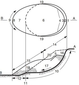
Gambar 1.6 Definisi fitur-fitur longsor: bagian atas, denah tipikal longsor di mana garis putus-putus menunjukkan jejak permukaan tanah yang pecah; bagian bawah, bagian di mana arsiran menunjukkan tanah yang tidak terganggu dan bintik-bintik menunjukkan luasnya material yang dipindahkan. Angka mengacu pada dimensi yang ditentukan dalam Tabel 1.1 (Komisi IAEG tentang Tanah longsor, 1990).

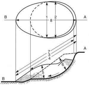
Gambar 1.7 Definisi dimensi longsor: bagian atas, denah tipikal longsor di mana garis putus-putus merupakan jejak permukaan tanah yang pecah; bagian bawah, bagian di mana arsiran menunjukkan tanah tidak terganggu, bintik-bintik menunjukkan luasnya material yang dipindahkan, dan garis putus-putus adalah permukaan tanah asli. Angka mengacu pada dimensi yang ditentukan dalam Tabel 1.2 (Komisi IAEG tentang Tanah longsor, 1990).


Referensi: Wyllie, Duncan C. Dan Mah, Christopher W (2004) Teknik lereng batu – sipil dan pertambangan edisi ke-4, London dan New York


Notice: Trying to access array offset on value of type bool in /home/abdiacom/domains/abdiyasa.com/public_html/home/wp-content/themes/betheme/functions/theme-functions.php on line 1599

Principle of Rock Slope Design – 1.2 Principles of rock slope engineering


Notice: Trying to access array offset on value of type bool in /home/abdiacom/domains/abdiyasa.com/public_html/home/wp-content/themes/betheme/functions/theme-functions.php on line 1599

1.2 Principles of rock slope engineering
This section describes the primary issues that need to be considered in rock slope design for civil projects and open pit mines. The basic difference between these two types of project are that in
civil engineering a high degree of reliability is required because slope failure, or even rock falls,
can rarely be tolerated. In contrast, some movement of open pit slopes is accepted if production
is not interrupted, and rock falls are of little consequence.

Figure 1.2 Relationship between slope height and slope angle for open pits, and natural and engineered slopes: (a) pit slopes and caving mines (Sjöberg, 1999); and (b) natural and engineered slopes in China (data from Chen (1995a,b)).

As a frame of reference for rock slope design, Figure 1.2 shows the results of surveys of the
slope height and angle and stability conditions for natural, engineered and open pit mine slopes
(Chen, 1995a,b; Sjöberg, 1999). It is of interest to note that there is some correspondence between the steepest and highest stable slopes for both natural and man-made slopes. The graphs also show that there are many unstable slopes at flatter angles and lower heights than the maximum values because weak rock or adverse structure can result in instability of even low slopes.

1.2.1 Civil engineering
The design of rock cuts for civil projects such as highways and railways is usually concerned
with details of the structural geology. That is, Principles of rock slope design 5 Figure 1.3 Cut face coincident with continuous, low friction bedding planes in shale on Trans Canada Highway near Lake Louise, Alberta. (Photograph by A. J. Morris.) the orientation and characteristics (such as length, roughness and infilling materials) of the joints, bedding and faults that occur behind the rock face. For example,

Figure 1.3 Cut face coincident with continuous, low friction bedding planes in shale on Trans Canada Highway near Lake Louise, Alberta. (Photograph by A. J. Morris.)

Figure 1.3 shows a cut slope in shale containing smooth bedding planes that are continuous over the full height of the cut and dip at an angle of about 50◦ towards the highway. Since the friction angle of these discontinuities is about 20–25◦, any attempt to excavate this cut at a steeper angle than the dip of the beds would result in blocks of rock sliding from the face on the beds; the steepest unsupported cut that can be made is equal to the dip of the beds. However, as the alignment of the road changes so that the strike of the beds is at right angles to the cut face (right side of photograph), it is not possible for sliding to occur on the beds, and a steeper face can be excavated.

For many rock cuts on civil projects, the stresses in the rock are much less than the rock strength so there is little concern that fracturing of intact rock will occur. Therefore, slope design is primarily concerned with the stability of blocks of rock formed by the discontinuities. Intact rock strength, which is used indirectly in slope design, relates to the shear strength of discontinuities and rock masses, as well as excavation methods and costs.

Figure 1.4 shows a range of geological conditions and their influence on stability, and illustrates the types of information that are important to design. Slopes (a) and (b) show typical conditions for sedimentary rock, such as sandstone and limestone containing continuous beds, on which sliding can occur if the dip of the beds is steeper than the friction angle of the discontinuity surface. In (a) the beds “daylight” on the steep cut face and blocks may slide on the bedding, while in (b) the face is coincident with the bedding and the face is stable. In (c) the overall face is also stable because the main discontinuity set dips into the face. However, there is some risk of instability of surficial blocks of rock formed by the conjugate joint set that dips out of the face, particularly if there has been blast damage during construction. In (d) the main joint set also dips into the face but at a steep angle to form a series of thin slabs that can fail by toppling where the center of gravity of the block lies outside the base. Slope (e) shows a typical horizontally bedded sandstone–shale sequence in which the shale weathers considerably faster than the sandstone to form a series of overhangs that can fail suddenly along vertical stress relief joints. Slope (f) is cut in weak rock containing closely spaced but low persistence joints that do not form a continuous sliding surface. A steep slope cut in this weak rock mass may fail along a shallow circular surface, partially along joints and partially through intact rock.

Figure 1.4 Influence of geological conditions on stability of rock cuts: (a) potentially unstable—discontinuities “daylight” in face; (b) stable slope—face excavated parallel to discontinuities; (c) stable slope—discontinuities dip into face; (d) toppling failure of thin beds dipping steeply into face; (e) weathering of shale beds undercuts strong sandstone beds to form overhangs; (f) potentially shallow circular failure in closely fractured, weak rock.


1.2.2 Open pit mining slope stability
The three main components of an open pit slope
design are as follows (Figure 1.5).

Figure 1.5 Typical open pit slope geometry showing relationship between overall slope angle, inter-ramp angle and bench geometry.


First, the overall pit slope angle from crest to toe, incorporates all ramps and benches. This may be a composite slope with a flatter slope in weaker, surficial materials, and a steeper slope in more competent rock at depth. In addition, the slope angle may vary around the pit to accommodate both differing geology and the layout of the ramp. Second, the inter-ramp angle is the slope, or slopes, lying between each ramp that will depend on the number of ramps and their widths. Third,  the face angle of individual benches depends on vertical spacing between benches, or combined multiple benches, and the width of the benches required to contain minor rock falls.

Some of the factors that may influence slope design are the slope height, geology, rock strength, ground water pressures and damage to the face by blasting. For example, with each successive push-back of a slope, the depth of the pit will increase and there may need to be a corresponding decrease in the overall slope angle. Also, for slopes on which the ramp is located, the slope angle may be flatter to limit the risk of failures that take out the ramp, compared to slopes with no ramp where some instability may be tolerated. Where there is significant water pressure in the slope, consideration may be given to installing a drainage system if it can be shown that a reduction in water pressure will allow the slope angle to be increased. For deep pits where an increase in slope angle of one or two degrees will result in a saving of several million cubic meters of rock excavation, an extensive drainage system may be justified. Such drainage systems could comprise fans of holes with lengths of hundreds of meters drilled from the slope face, or a drainage adit with holes drilled into the rock above the tunnel.

With respect to the bench face angle, this may be governed by the orientation of a predominant joint set if there are joints that dip out of the face at a steep angle. If this situation does not exist, then the bench angle will be related to the overall slope geometry, and whether single benches are combined into multiple benches. One factor that may influence the maximum height of individual benches is the vertical reach of excavating equipment, to limit the risk accidents due to collapse of the face.

In order to provide a guideline on stable pit slope angles, a number of studies have been carried out showing the relationship between slope angle, slope height and geology; the records also distinguished whether the slopes were stable or unstable (see Figure 1.2). These studies have been made for both open pit mine slopes (Sjöberg, 1999), and natural and engineered slopes in China (Chen, 1995a,b). As would be expected, if the slopes were not selected according to geology, there is little correlation between slope height and angle for stable slopes. However, sorting of the data according to rock type and rock strength shows a reasonable correlation between slope height and angle for each classification.

1.3 Slope features and dimensions
The International Association of Engineering Geology has prepared definitions of landslide features and dimensions as shown in Figures 1.6 and 1.7 (IAEG, 1990; TRB, 1996). Although the diagrams depicting the landslides show soil-type slides with circular sliding surfaces, many of these landslide features are applicable to both rock slides and slope failures in weak and weathered rock. The value of the definitions shown in  Figures 1.6 and 1.7 is to encourage the use of consistent terminology that can be clearly understood by others in the profession when investigating and reporting on rock slopes and landslides.

Figure 1.6 Definitions of landslide features: upper portion, plan of typical landslide in which dashed line indicates trace of rupture surface on original ground surface; lower portion, section in which hatching indicates undisturbed ground and stippling shows extent of displaced material. Numbers refer to dimensions defined in Table 1.1 (IAEG Commission on Landslides, 1990).

Figure 1.7 Definitions of landslide dimensions: upper portion, plan of typical landslide in which dashed line is trace of rupture surface on original ground surface; lower portion, section in which hatching indicates undisturbed ground, stippling shows extent of displaced material, and broken line is original ground surface. Numbers refer to dimensions defined in Table 1.2 (IAEG Commission on Landslides, 1990).


References : Wyllie, Duncan C. And Mah, Christopher W  (2004) Rock slope engineering – civil and mining 4th edition, London and New York